NEHRP Recommended Seismic
Provisions for New and Other Structures
The NEHRP Recommended Seismic Provisions for New and Other
Structures is available:
Guide to Using the
2020 NEHRP Provisions
Part
1 of the Provisions provides recommended changes to the seismic
requirements of
ASCE 7-16, Chapters 11 to 22. For a given chapter, only those
sections
with
recommended modifications or additions are shown. Therefore, the
Provisions
Part 1 should be used side-by-side with ASCE 7-16 in order to
grasp the
full
context of each chapter.
Part
2 of the Provisions provides a complete commentary for each
chapter. It
is
comprised of the new commentary to each proposed change
contained in
Part 1
along with the existing ASCE 7-16 commentary to unchanged
sections.
Therefore,
the Part 2 Commentary is self-contained. Black bars
in the columns indicate new
commentary
matching Provisions Part 1
changes.
Part
3 provides resource papers adopted in the 2020 Provisions cycle.
These
resource
papers are self- contained and not necessarily directly
associated with
a Part
1 provision. They are not written in standards language format.
The table
in the Introduction provides
a summary of Part 1 topics along with reference
sections in Parts
1 and 2, and any
relevant resource
paper in Part 3.
COMMENTARY
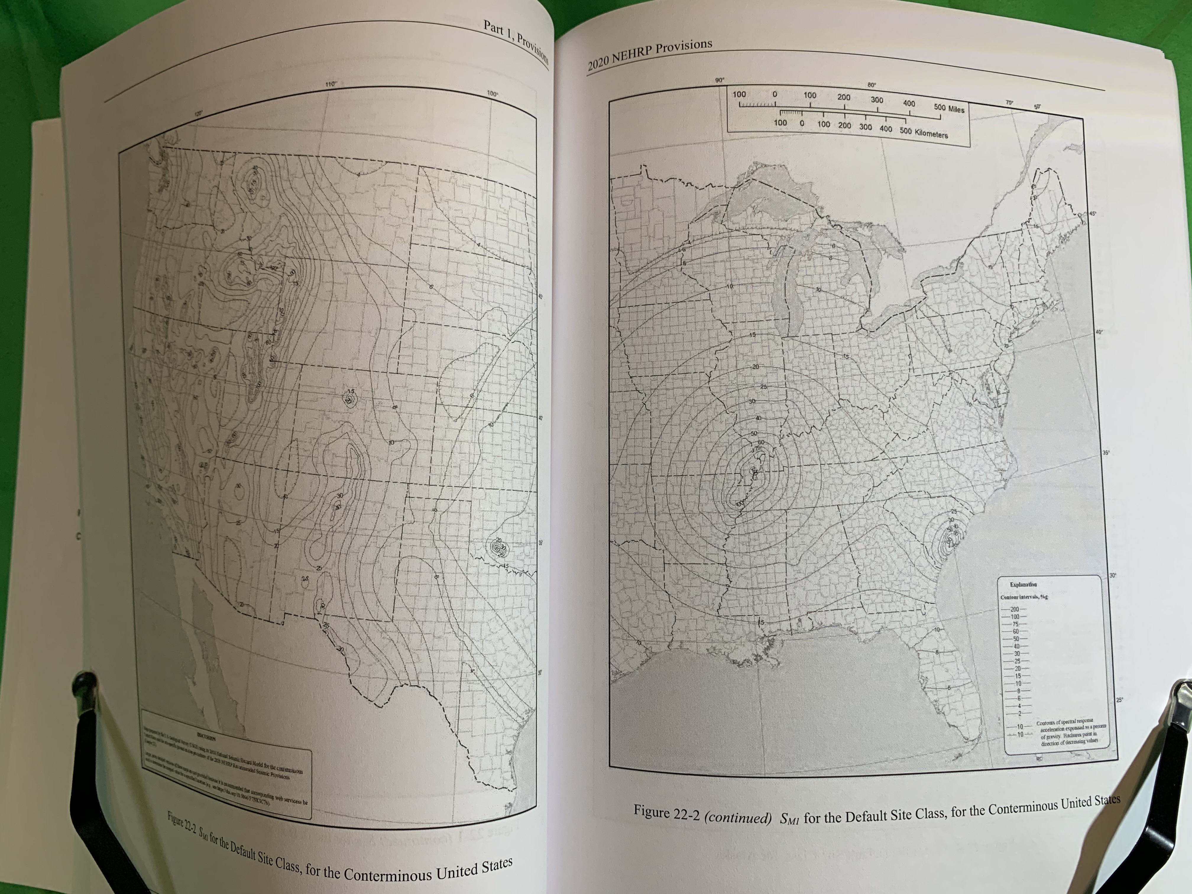
TO CHAPTER 22, SEISMIC GROUND MOTION AND
LONG-PERIOD TRANSITION
MAPS
524
APPENDIX PROJECT PARTICIPANTS...........................................................................................
546
SECTION
11.8 GEOLOGIC HAZARDS AND GEOTECHNICAL INVESTIGATION................................
20
11.8.1
Site
Limitation for Seismic Design Categories E and F......................................................
20
11.8.2
Geotechnical
Investigation Report Requirements for Seismic Design
Categories C
through F
20
11.8.3
Additional
Geotechnical Investigation Report Requirements for Seismic
Design
Categories D through
F........
20
SECTION
11.9 VERTICAL GROUND MOTIONS FOR
SEISMIC DESIGN.................................................
21
11.9.1
General.........................................................................................................................................
21
11.9.2
MCER
Vertical
Response Spectrum.......................................................................................
21
11.9.3
Design
Vertical Response Spectrum......................................................................................
22
Return to top
BUILDING
STRUCTURES......... 24
SECTION
12.2.1 SEISMIC FORCE-RESISTING SYSTEM SELECTION AND LIMITATIONS.............
24
12.2.1.1
Alternative
Seismic
Force-Resisting
Systems......................................................................
25
12.2.1.2
Elements
of
Seismic
Force-Resisting
Systems.....................................................................
25
SECTION
12.2.3.2 TWO-STAGE ANALYSIS PROCEDURE...........................................................................
26
12.2.3.2.1
Vertical
Combinations of Systems.........................................................................................
26
12.2.3.2.2
One-Story
Structures with Flexible Diaphragms and Rigid
Vertical Elements.............. 26
SECTION
12.2.5
SYSTEM-SPECIFIC REQUIREMENTS.................................................................................
27
12.2.5.4
Increased
Structural Height
Limit for Steel
Eccentrically Braced Frames, Steel
Special
Concentrically Braced Frames, Steel
Buckling-Restrained Braced Frames,
Steel
Special Plate Shear Walls, Steel and Concrete Coupled
Composite Plate
Shear
Walls, Reinforced
Concrete Ductile Coupled Walls, and
Special
Reinforced
Concrete Shear
Walls................................................................................................................
27
SECTION
12.3.2 IRREGULAR AND
REGULAR CLASSIFICATION............................................................
27
12.3.2.2
Vertical Irregularity..................................................................................................................
27
SECTION
12.3.3 LIMITATIONS AND ADDITIONAL
REQUIREMENTS FOR SYSTEMS
WITH STRUCTURAL IRREGULARITIES............................................................................................
30
12.3.3.1
Prohibited
Vertical Irregularities for Seismic Design Categories D through F...............
30
12.3.3.2
Extreme Weak
Stories...............................................................................................................
30
12.3.3.3
Elements
Supporting Discontinuous Walls or
Frames........................................................
30
12.3.3.4
Increase
in
Forces Caused by Irregularities for Seismic Design
Categories D
through
F.....................................................................................................................................
30
SECTION 12.3.4 REDUNDANCY.............................................................................................................................
30
12.3.4.1
Conditions
Where Value of ρ is
1.0........................................................................................
31
12.3.4.2
Redundancy
Factor, ρ, for Seismic Design Categories D through
F................................
31
SECTION
12.5.3
SEISMIC DESIGN CATEFORY C...........................................................................................
31
12.5.3.1
Structures
with Horizontal Structural Irregularities..............................................................
31
SECTION
12.6
ANALYSIS
PRODECURE SELECTION...................................................................................
32
SECTION
12.7.3
STRUCTURAL MODELING.....................................................................................................
32
SECTION
12.8.6
DISPLACEMENT AND DRIFT DETERMINATION...........................................................
32
12.8.6.1
Minimum
Base
Shear for Computing Displacement and
Drift..........................................
32
12.8.6.2
Period
for
Computing Displacement
and Drift.....................................................................
32
12.8.6.3
Design
Earthquake and Maximum Considered
Earthquake Displacement..................... 32
12.8.6.4
Design
Story
Drift
Determination...........................................................................................
33
SECTION
12.9.1.4.2
SCALING OF DISPLACEMENTS AND DRIFTS.........................................................
33
SECTION
12.10
DIAPHRAGMS, CHORDS AND COLLECTORS..................................................................
33
12.10.4
Alternative
Diaphragm Design Provisions for One-Story Structures with
Flexible
Diaphragms and Rigid
Vertical
Elements........
34
14.5.2.1.2
Terminology........................................................................................................
66
14.5.2.2
Application Requirements.......................................................................................................
67
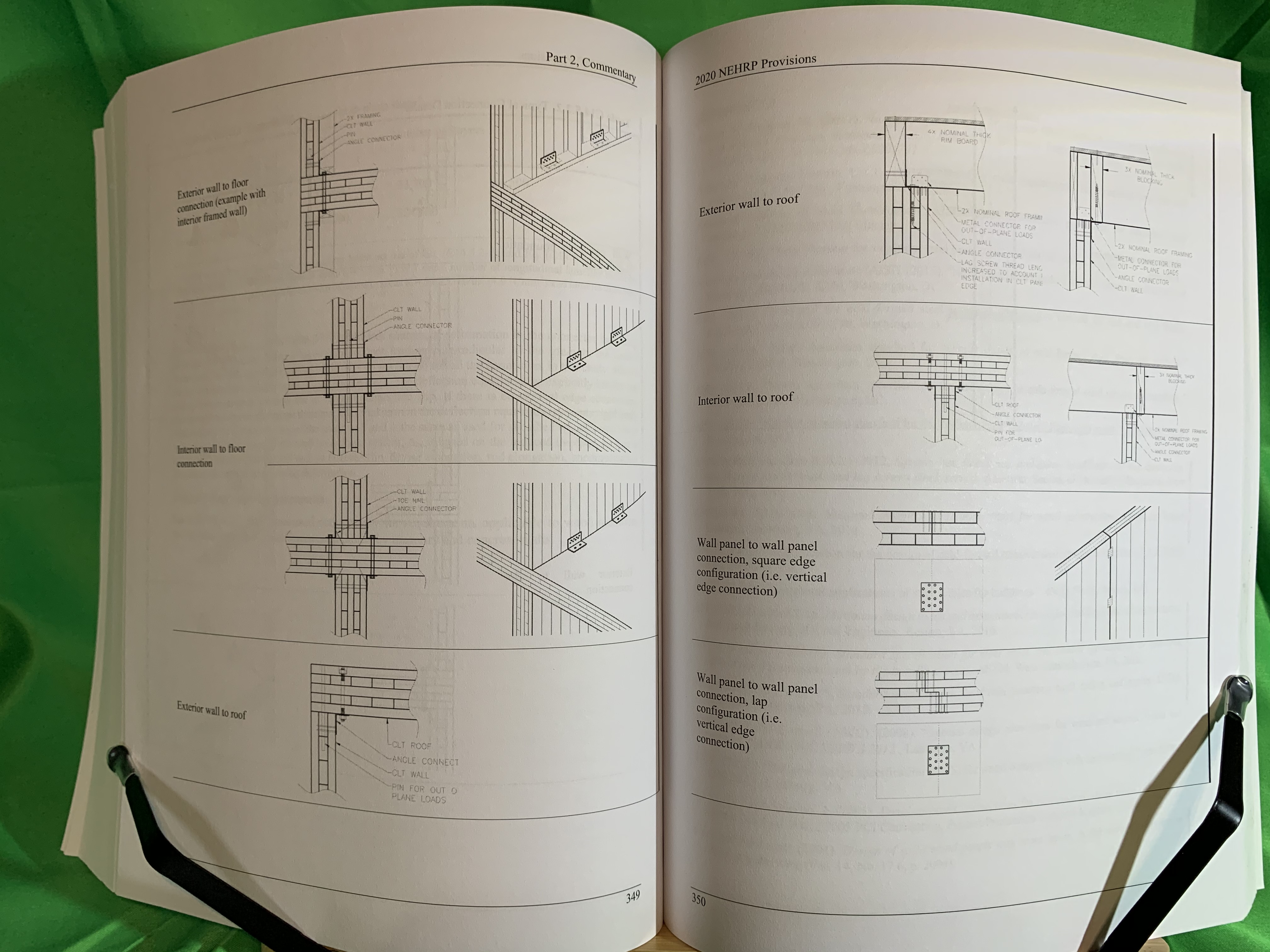
14.5.2.3
CLT
Shear
Wall Requirements..............................................................................................
68
14.5.2.3.1
CLT
panels..........................................................................................................
68
14.5.2.3.2
Top-
and
bottom-of-wall angle connector....................................................
68
14.5.2.3.3
Adjoining
panel
edge connector....................................................................
69
14.5.2.3.4
Hold-down system............................................................................................
70
14.5.2.3.5
Compression zone.............................................................................................
70
14.5.2.3.6
Other
load
path connections to CLT
wall panels.........................................
70
14.5.2.3.7
CLT
shear
walls with shear resistance provided by high aspect ratio
panels
only
71
14.5.2.4
Deflection....................................................................................................................................
71
14.5.2.5
Nominal
unit
shear
capacity....................................................................................................
71
14.5.2.6
ASD
and LRFD
design unit shear capacities.......................................................................
72
14.5.2.7
Diaphragm Requirements........................................................................................................
72
Return to top
NONBUILDING STRUCTURES................... 74
SECTION
15.2
NONBUILDING STRUCTURES CONNECTED BY NONSTRUCTURAL COMPONENTS
TO
OTHER
ADJACENT STRUCTURES.......
74
15.2.1
Nonbuilding
Structures Connected by Nonstructural Components to Other
Adjacent
Structures 74
15.2.2
Architectural,
Mechanical, and Electrical Components Spanning
Between
Nonbuilding Structures.............................................................................................................
74
SECTION
15.3
NONBUILDING STRUCTURES SUPPORTED BY
OTHER STRUCTURES.................. 74
15.3.1
Less
Than 20%
Combined
Weight Condition......................................................................
74
15.3.2
Supported
Nonbuilding Structures with Greater Than or Equal to 20%
Combined
Weight
75
15.3.3
Architectural,
Mechanical, and Electrical Components Supported by
Nonbuilding
Structures
75
Return to top
SYSTEMS..........
77
SECTION
18.2.3.2
EQUIVALENT LATERAL FORCE PROCEDURE...........................................................
77
Return to top
SEISMIC
DESIGN........................................
79
SECTION
19.3
FOUNDATION EFFECTS..............................................................................................................
79
19.3.1
Foundation Damping
Requirements.......................................................................................
79
19.3.2
Effective Damping
Ratio..........................................................................................................
79
19.3.3
Radiation
Damping for Rectangular Foundations...............................................................
81
19.3.4
Radiation
Damping for Circular Foundations......................................................................
83
19.3.5
Soil Damping..............................................................................................................................
84
Return to top
SEISMIC
DESIGN..................................
86
SECTION
20.1
SITE CLASSIFICATION................................................................................................................
86
SECTION
20.2 SITE CLASS DEFINITIONS.........................................................................................................
86
20.2.1
Site Class
F..................................................................................................................................
87
20.2.2
Site
Class E
(Soft Clay)............................................................................................................
87
20.2.3
Site
Classes
C, CD, D, DE and
E............................................................................................
87
20.2.4
Site
Class B
and BC (Medium Hard and
Soft Rock)...........................................................
87
20.2.5
Site
Class A
(Hard Rock).........................................................................................................
87
SECTION
20.3
ESTIMATION OF SHEAR WAVE VELOCITY PROFILES.................................................
88
SECTION
20.4
DEFINITIONS OF SITE CLASS PARAMETERS....................................................................
88
C11.8
GEOLOGIC HAZARDS AND
GEOTECHNICAL
INVESTIGATION...............................................
132
C11.8.1
Site Limitation for Seismic Design Categories E and F........................................................
132
C11.8.2
Geotechnical
Investigation Report Requirements for Seismic Design
Categories C through
F
132
C11.8.3
Additional
Geotechnical Investigation Report Requirements for Seismic
Design Categories
D
through F.......
132
C11.9
VERTICAL GROUND MOTIONS FOR SEISMIC DESIGN................................................................
134
C11.9.1 General...........................................................................................................................................
134
C11.9.2
MCER
Vertical Response Spectrum..........................................................................................
134
REFERENCES.............................................................................................................................................................
137
OTHER
REFERENCES (NOT CITED).................................................................................................................
138
Return to top
STRUCTURES
140
C12.1
STRUCTURAL
DESIGN BASIS............................................................................................................
140
C12.1.1 Basic Requirements.....................................................................................................................
140
C12.1.2
Member Design, Connection Design, and Deformation Limit............................................
144
C12.1.3
Continuous
Load Path and
Interconnection............................................................................
144
C12.1.4
Connection to Supports...............................................................................................................
144
C12.1.5 Foundation Design........................................................................................................................
145
C12.1.6
Material
Design and Detailing Requirements.........................................................................
145
C12.2
STRUCTURAL SYSTEM SELECTION....................................................................................................
145
C12.2.1
Seismic Force-Resisting System Selection and Limitations.................................................
145
C12.2.1.1
Alternative Structural Systems...........................................................................
149
C12.2.1.2
Elements of Seismic
Force-Resisting Systems................................................
150
C12.2.2
Combinations of Framing Systems in
Different Directions..................................................
151
C12.2.3
Combinations
of Framing Systems in the Same Direction....................................................
151
C12.2.3.1
R, Cd, and Ω0
Values for
Vertical Combinations........................................... 151
C12.2.3.2
Two-Stage Analysis Procedure...........................................................................
151
C12.2.3.3
R, Cd ,
and Ω0
Values for Horizontal Combinations........................................
152
C12.2.4
Combination Framing
Detailing Requirements......................................................................
152
C12.2.5 System-Specific Requirements..................................................................................................
152
C12.2.5.1 Dual System...........................................................................................................
152
C12.2.5.2
Cantilever Column Systems................................................................................
153
C12.2.5.3
Inverted
Pendulum-Type
Structures..................................................................
153
C12.2.5.4
Increased Structural Height Limit for Steel
Eccentrically Braced Frames, Steel
Special
Concentrically Braced Frames, Steel
Buckling- Restrained
Braced
Frames,
Steel
Special Plate Shear Walls, and Special
Reinforced Concrete
Shear
Walls...................................................
153
C12.2.5.5
Special
Moment Frames in Structures Assigned to Seismic Design Categories
D
through F.............
153
C12.2.5.6
Steel Ordinary Moment Frames.........................................................................
154
C12.2.5.6.1
Seismic Design Category D or E....................................................................
155
C12.2.5.6.2
Seismic
Design
Category F..............................................................................
156
C12.2.5.7
Steel Intermediate
Moment Frames..................................................................
156
C12.2.5.7.1
Seismic Design Category
D.............................................................................
156
C12.2.5.7.2
Seismic
Design
Category E..............................................................................
156
C12.2.5.7.3
Seismic Design Category
F..............................................................................
156
C12.2.5.8
Shear Wall–Frame Interactive Systems............................................................
156
C12.3
DIAPHRAGM FLEXIBILITY, CONFIGURATION
IRREGULARITIES, AND
REDUNDANCY...........................................................................................................................................
157
C12.3.1 Diaphragm Flexibility..................................................................................................................
157
C12.3.1.1
Flexible Diaphragm Condition...........................................................................
157
C21.4
DESIGN
ACCELERATION PARAMETERS...........................................................................................
519
C21.5
MAXIMUM CONSIDERED EARTHQUAKE GEOMETRIC MEAN
(MCEG )
PEAK
GROUND ACCELERATION...................................................................................................................
520
REFERENCES.............................................................................................................................................................
520
OTHER
REFERENCES (NOT CITED).................................................................................................................
522
Return to top
MAPS
524
RISK-TARGETED
MAXIMUM CONSIDERED EARTHQUAKE (MCER )
SPECTRAL
RESPONSE ACCELERATIONS.............................................................................................................
539
MAXIMUM
CONSIDERED
EARTHQUAKE GEOMETRIC MEAN (MCEG )
PEAK GROUND
ACCELERATIONS..........
541
LONG-PERIOD TRANSITION
MAPS..................................................................................................................
541
USGS
SEISMIC DESIGN
GEODATABASE AND WEB SERVICE..............................................................
542
REFERENCES.............................................................................................................................................................
542
Return to top APPENDIX PROJECT PARTICIPANTS...........................................................................................
546
intentionally
left blank.
APPENDIX
PROJECT
PARTICIPANTS
BSSC Provisions
Update Committee
Chair
David
Bonneville
Degenkolb
Engineers
Voting
Member
Peter
Carrato
Bechtel
Power Corporation
Voting
Member
Kelly
Cobeen
Wiss,
Janney, Elstner Associates
Voting
Member
C.B.
Crouse
AECOM
Voting
Member
Dan
Dolan
Washington
State University
Voting
Member
Anindya
Dutta
Simpson
Gumpertz & Heger
Voting
Member
S.K.
Ghosh
S.K.
Ghosh Associates
Voting
Member
John
Gillengerten
SE,
Retired OSHPD
Voting
Member
Ron
Hamburger
Simpson
Gumpertz & Heger
Voting
Member
Jim
Harris
James
Harris & Associates
Voting
Member
William
Holmes
Rutherford
+ Chekene
Voting
Member
John
Hooper
Magnusson
Klemencic Associates
Voting
Member
Gyimah
Kasali
Rutherford
+ Chekene
Voting
Member
Charles
Kircher
Charles
Kircher & Associates
Voting
Member
Philip
Line
American
Wood Council
Voting
Member
Bret
Lizundia
Rutherford
+ Chekene
Voting
Member
James
Malley
Degenkolb
Engineers
Voting
Member
Bonnie
Manley
American
Iron and Steel Institute
Voting
Member
Robert
Pekelnicky
Degenkolb
Engineers
Voting
Member
Rafael
Sabelli
Walter
P. Moore
Voting
Member
John
Silva
Hilti
Voting
Member
J. G.
(Greg) Soules
CB&I
Storage Tank Solutions
Voting
Member
Jonathan
Stewart
University
of California, Los Angeles
FEMA
technical advisor
and
representative
Robert
Hanson
University
of Michigan (Professor Emeritus)
FEMA
representative
Mai Tong
Federal
Emergency Management Agency
USGS
representative
Nicolas
Luco
U.S.
Geological Survey
USGS
representative
Sanaz
Rezaeian
U.S.
Geological Survey
NIST
representative
Steven
McCabe
National
Institute of Standards and Technology
NIST
representative
Matthew
Speicher
National
Institute of Standards and Technology
NIBS
Staff
Jiqiu
(JQ) Yuan
National
Institute of Building Sciences
BSSC Project 17
Committee on Seismic Design Value Maps
Chair
Ron
Hamburger
Simpson
Gumpertz & Heger
Voting
Member
Norm
Abrahamson
University
of California Berkeley
Voting
Member
David
Bonneville
Degenkolb
Engineers
Voting
Member
C.B.
Crouse
AECOM
Voting
Member
Dan Dolan
Washington
State University
Voting
Member
Julie
Furr
Rimkus
Consulting Group
Voting
Member
Jim
Harris
James
Harris & Associates
Voting
Member
Jon
Heintz
Applied
Technology Council
Voting
Member
William
Holmes
Rutherford
+ Chekene
Voting
Member
John
Hooper
Magnusson
Klemencic Associates
Voting
Member
Charles
Kircher
Charles
Kircher & Associates
Voting
Member
Robert
Pekelnicky
Degenkolb
Engineers
Voting
Member
Jon Siu
City of
Seattle, Washington
Voting
Member
Jonathan
Stewart
University
of California, Los Angeles
USGS
representative
Nicolas
Luco
U.S.
Geological Survey
USGS
representative
Sanaz
Rezaeian
U.S.
Geological Survey
FEMA
technical advisor and representative
Robert
Hanson
University
of Michigan (Professor Emeritus)
FEMA
representative
Mai Tong
Federal
Emergency Management Agency
NIST
representative
Steven
McCabe
National Institute
of Standards and
Technology
NIST
representative
Siamak
Sattar
National
Institute
of Standards and
Technology
NIBS
Staff
Jiqiu
(JQ) Yuan
National
Institute of Building Sciences
PUC Issue Teams
IT 1,
Seismic Performance Objectives
Chair
Robert
Pekelnicky
Degenkolb
Engineers
Voting
Member
Ibbi
Amufti
Arup
Voting
Member
David
Bonneville
Degenkolb
Engineers
Voting
Member
Julie
Furr
Rimkus
Consulting Group
Voting
Member
Ron
Hamburger
Simpson
Gumpertz & Heger
Voting
Member
Jim
Harris
James
Harris & Associates
Voting
Member
Jon
Heintz
Applied
Technology Council
Voting
Member
John
Hooper
Magnusson
Klemencic Associates
Voting
Member
Steven
McCabe
National
Institute of Standards and
Technology
Voting
Member
Maryann
Phipps
Estructure
Voting
Member
John
Silva
Hilti
Voting
Member
J. G.
(Greg) Soules
CB&I
Storage Tank Solutions
Corresponding
Member
David
Bonowitz
David
Bonowitz, S.E.
Corresponding
Member
Dan
Dolan
Washington
State University
Corresponding
Member
John
Gillengerten
SE,
Retired OSHPD
Corresponding
Member
Philip
Line
American
Wood Council
Corresponding
Member
Nicolas
Luco
U.S.
Geological Survey
Corresponding
Member
Terry
Lundeen
Coughlin
Porter Lundeen
Corresponding
Member
Kevin
Moore
Simpson
Gumpertz & Heger
Corresponding
Member
Rob
Smith
Arup
Corresponding
Member
Jeffrey
Soulages
Intel
Corporation
IT
2, Seismic-Force Resisting Systems and Design
Coefficients
Chair
Conrad
"Sandy"
Hohener
Degenkolb
Engineers
Voting
Member
Dan
Dolan
Washington
State University
Voting
Member
Edwin
Huston
Smith
& Huston
Voting
Member
Bret
Lizundia
Rutherford
+ Chekene
Voting
Member
Kevin
Moore
Simpson
Gumpertz & Heger
Voting
Member
Tom Xia
DCI
Engineers
Corresponding
Member
Richard
Bennett
University
of Tennessee
Corresponding
Member
Hussain
Bhatia
OSHPD
Corresponding
Member
Bonnie
Manley
Steel
Market Develop Insitute
Corresponding
Member
Dan
Sloat
Degenkolb
Engineers
Corresponding
Member
J. G.
(Greg) Soules
CB&I
Storage Tank Solutions
Corresponding
Member
Taka
Tamiya
Degenkolb
Engineers
Corresponding
Member
Robert
Tremblay
Polytechnique
IT 3,
Modal Response Spectrum Analys Considerations
Chair
Anindya
Dutta
Simpson
Gumpertz & Heger
Voting
Member
Kevin
Aswegan
Magnusson
Klemencic Associates
Voting
Member
Robert
Hanson
University
of Michigan
Voting
Member
Jay
Harris
National
Institute of Standards and
Technology
Voting
Member
James
Malley
Degenkolb
Engineers
Voting
Member
Rafael
Sabelli
Walter
P. Moore
Corresponding
Member
Jason
Collins
PCS
Structural Solutions
Corresponding
Member
Finley
Charney
Virginia
Tech
Corresponding
Member
Rob
Tovani
Computers
and Structures,
IT
4, Shear Wall Design
Chair
S.K.
Ghosh
S. K.
Ghosh Associates
Voting
Member
Dick
Bennett
University
of Tennessee
Voting
Member
Michel
Bruneau
University
of Buffalo
Voting
Member
Kelly
Cobeen
Wiss,
Janney, Elstner Associates
Voting
Member
Jason
Collins
PCS
Structural Solutions
Voting
Member
David
Fields
Magnusson
Klemencic Associates
Voting
Member
Gino
Kurama
University
of Notre Dame
Voting
Member
Andy
Taylor
KPFF
Consulting Engineers
Corresponding
Member
Kevin
Aswegan
Magnusson
Klemencic Associates
Corresponding
Member
Jeff
Berman
University
of Washington
Corresponding
Member
Daniel
Borello
Oregon
State University
Corresponding
Member
Dan
Dolan
Washington
State University
Corresponding
Member
Anindya
Dutta
Simpson
Gumpertz & Heger
Corresponding
Member
Larry
Fahnestock
University
of Illinois at Urbana-Champaign
Corresponding
Member
Joe
Ferzli
Cary
Kopczynski & Company
Corresponding
Member
John
Hooper
Magnusson
Klemencic Associates
Corresponding
Member
Dawn
Lehman
University
of Washington
Corresponding
Member
Philip
Line
American
Wood Council
Corresponding
Member
Bonnie
Manley
American
Iron and Steel Institute
Corresponding
Member
Joe
Maffei
Maffei
Structural Engineering
Corresponding
Member
Jack
Moehle
University
of California Berkeley
Corresponding
Member
Lawrence
Novak
Portland
Cement Association
Corresponding
Member
Laura
Lowes
University
of Washington
Corresponding
Member
Jose
Restrepo
University
of California, San Diego
Corresponding
Member
Rafael
Sabelli
Walter
P. Moore
Corresponding
Member
Siamak
Sattar
National
Institute of Standards and
Technology
Corresponding
Member
Amit
Varma
Purdue
University
Corresponding
Member
John
Wallace
University
of California, Los Angeles
Corresponding
Member
Andrew
Whittaker
University
of Buffalo
Corresponding
Member
Tom Xia
DCI
Engineers
Corresponding
Member
Kirsten
Zeydel
ZO
Consulting
IT 5,
Nonstructural Components
Chair
John
Gillengerten
SE,
Retired OSHPD
Voting
Member
Peter
Carrato
Bechtel
Power Corporation
Voting
Member
Travis
Churpalo
Degenkolb
Engineers
Voting
Member
William
Holmes
Rutherford
+ Chekene
Voting
Member
Bret
Lizundia
Rutherford
+ Chekene
Voting
Member
John
Silva
Hilti
Voting
Member
J. G.
(Greg) Soules
CB&I
Storage Tank Solutions
Voting
Member
Chris
Tokas
OSHPD
Corresponding
Member
Hussain
Bhatia
OSHPD
Corresponding
Member
Phil
Caldwell
Schneider
Corresponding
Member
Meaghan
Halligan
ISAT
Corresponding
Member
Matthew
Hoehler
National
Institute of Standards and
Technology
Corresponding
Member
Robert
Pekelnicky
Degenkolb
Engineers
Corresponding
Member
Maryann
Phipps
Estructure
Corresponding
Member
Robert
Simmons
Petra
Seismic Design
Corresponding
Member
Siavash
Soroushian
Arup
IT
6, Nonbuilding Structures
Chair
Peter
Carrato
Bechtel
Power Corporation
Voting
Member
J. G.
(Greg) Soules
CB&I
Storage Tank Solutions
Voting
Member
Bill
Scott
AISC
Industrial building committee
Voting
Member
Eric Wey
Fluor
Corresponding
Member
Rick
Drake
Fluor
Corresponding
Member
John
Rolfes
Computerized
Structural Design
Corresponding
Member
Robert
Simmons
Petra
Seismic / ASHRAE
Corresponding
Member
John
Silva
Hilti
Corresponding
Member
Harold
Sprague
Parsons
IT
7, Soil-Foundation Interaction
Chair
Stephen
Harris
Simpson
Gumpertz & Heger
Voting
Member
C.B.
Crouse
AECOM
Voting
Member
Gyimah
Kasali
Rutherford
+ Chekene
Voting
Member
Ian
McFarlane
Magnusson
Klemencic Associates
Voting
Member
Robert
Pekelnicky
Degenkolb
Engineers
Voting
Member
Jonathan
Stewart
University
of California, Los Angeles
Corresponding
Member
Bruce
Kutter
University
of California Davis
Corresponding
Member
Armin
Masroor
Arup
IT 8,
Base Isolation and Energy Dissipation
Deactivated
IT
9, Diaphragm Issues - RWFD and Alternate Provisions
for Diaphragm Design
Chair
Kelly
Cobeen
Wiss,
Janney, Elstner Associates
Voting
Member
John
Lawson
Cal Poly
San Luis Obispo
Voting
Member
S.K.
Ghosh
S. K.
Ghosh Associates
Voting
Member
Ron La
Plante
California
Division of the State Arch
Voting
Member
Ben
Schafer
Johns
Hopkins University
Voting
Member
Tom
Sabol
Engelkirk
& Sabol
Corresponding
Member
Pouria
Bahmani
KPFF
Consulting Engineers
Corresponding
Member
Patrick
Bodwell
Vulcraft/
Verco Group
Corresponding
Member
Dan
Dolan
Washington
State Universtiy
Corresponding
Member
Matt
Eatherton
Virginia
Tech
Corresponding
Member
Andre
Filiatrault
SUNY
University at Buffalo
Corresponding
Member
Christopher
Gill
Hilti
North America
Corresponding
Member
Dave
Golden
ASC
Steel Deck Div. of ASC Profiles
Corresponding
Member
Jerome
(Jerry) Hajjar
Northeastern
University
Corresponding
Member
Steve
Hobbs
Vulcraft
Corresponding
Member
Maria
Koliou
Colorado
State University
Corresponding
Member
William
Holmes
Rutherford
+ Chekene
Corresponding
Member
Philip
Line
American
Wood Council
Corresponding
Member
Bonnie
Manley
American
Iron and Steel Institute
Corresponding
Member
Scott
Schiff
Applied
Technology Council
Corresponding
Member
Walt
Schultz
Nucor
Corresponding
Member
Andrew
Shuck
Wiss,
Janney, Elstner Associates
Corresponding
Member
Robert
Tremblay
Polytechnique
Montreal
Corresponding
Member
Tom Xia
DCI
Engineers
IT
10, Seismic Design Value Maps
Chair
C.B.
Crouse
AECOM
Voting
Member
Ron
Hamburger
Simpson
Gumpertz & Heger
Voting
Member
Jim
Harris
James
Harris & Associates
Voting
Member
William
Holmes
Rutherford
+ Chekene
Voting
Member
John
Hooper
Magnusson
Klemencic Associates
Voting
Member
Charles
Kircher
Charles
Kircher & Associates
Voting
Member
Nicolas
Luco
U.S.
Geological Survey
Voting
Member
Sanaz
Razaeian
U.S.
Geological Survey
Voting
Member
Jonathan
Stewart
University
of California Los Angeles
Project 17 Work
Groups
WG1,
Uncertainty and Precision
Chair
Dan
Dolan
Washington
State University
Member
Ben
Enfield
City of
Seattle Building Department
Member
Jon
Heintz
Applied
Technology Council
Member
Nicolas
Luco
U.S.
Geological Survey
Member
Robert
Pekelnicky
Degenklob
Engineers
WG2,
Acceptable Risk
Chair
Robert
Pekelnicky
Degenkolb
Engineers
Member
Ibbi
Amufti
ARUP
Member
Jack
Baker
Stanford
University
Member
C.B.
Crouse
AECOM
Member
Jon
Heintz
Applied
Technology Council
Member
William
Holmes
Rutherford
+ Chekene
Member
John
Hooper
Magnusson
Klemencic Associates
Member
Charles
Kircher
Charles
Kircher & Associates
Member
Nicolas
Luco
U.S.
Geological Survey
Member
Siamak
Sattar
National Institute
of Standards and
Technology
Member
Jonathan
Stewart
University
of California, Los Angeles
WG3,
Multi-Period Spectral Parameters
Chair
Charles
Kircher
Charles
Kircher & Associates
Member
David
Bonneville
Degenkolb
Engineers
Member
C.B.
Crouse
AECOM
Member
John
Hooper
Magnusson
Klemencic Associates
Member
Nicolas
Luco
U.S.
Geological Survey
Member
Sanaz
Rezaeian
U.S.
Geological Survey
Member
Jonathan
Stewart
University
of California, Los Angeles
WG4,
Deterministic Maps
Chair
C.B.
Crouse
AECOM
Member
Ned
Field
U.S.
Geological Survey
Member
John
Hooper
Magnusson
Klemencic Associates
Member
Charles
Kircher
Charles
Kircher & Associates
Member
Nicolas
Luco
U.S.
Geological Survey
Member
Sanaz
Rezaeian
U.S.
Geological Survey
Member
Jonathan
Stewart
University
of California, Los Angeles
WG5,
Seismic Design Category
Chair
Julie
Furr
Rimkus
Consulting Group
Member
Dan Dolan
Washington
State University
Member
Jim
Harris
James
Harris & Associates
Member
William
Holmes
Rutherford
+ Chekene
Member
John
Hooper
Magnusson
Klemencic Associates
Member
Robert
Pekelnicky
Degenkolb
Engineers
Member
Jon Siu
City of
Seattle, Washington
Member
Paul
Timko
Cromwell
Architects Engineers
Project
17 Planning and Advisory Committees
Project
17 Planning Committee Participants
Chair
Ronald
Hamburger
Simpson
Gumpertz & Heger Inc.
Member
David
Bonneville
Degenkolb
Engineers
Member
C.B.
Crouse
AECOM
Member
Edward
Field
U.S.
Geological Survey
Member
Arthur
Frankel
U.S.
Geological Survey
Member
Robert
Hanson
University
of Michigan (Emeritus)
Member
James
Harris
James
Harris & Associates
Member
William
Holmes
Rutherford
& Chekene
Member
John
Hooper
Magnusson
Klemencic Associates
Member
Charles
Kircher
Kircher
& Associates
Member
Nicolas
Luco
U.S.
Geological Survey
Member
Morgan
Moschetti
U.S.
Geological Survey
Member
Robert
Pekelnicky
Degenkolb
Engineers
Member
Mark
Petersen
U.S.
Geological Survey
Member
Peter
Powers
U.S.
Geological Survey
Member
Sanaz
Rezaeian
U.S.
Geological Survey
Member
Philip
Schneider
Building
Seismic Safety Council
Member
Mai Tong
Federal
Emergency Management Agency
Project
17 Advisory Committee
Chair
Jennifer
Goupil
American
Society of Civil Engineers
Member
Philip
Caldwell
Schneider
Electric
Member
John
Egan
Consulting
Engineer
Member
Gary
Ehrlich
National
Association of Home Builders
Member
Kevin
Moore
Simpson
Gumpertz & Heger
Member
Mike
Mota
Concrete
Reinforcing Steel Institute
Member
Adrian
Rodrigues-Merak
Virgina
Tech
Member
J. G.
(Greg) Soules
CB&I
Storage Tank Solutions
Member
Zia
Zafir
Kleinfelder
Project
Management
Project
Management
FEMA
Project Manager
Mai Tong
Federal
Emergency Management Agency
PUC
Chair
David
Bonneville
Degenkolb
Engineers
NIBS
Project Manager
Jiqiu
(JQ) Yuan
National
Institute of Building Sciences
NIBS
Project Manager
Philip
Schneider1
National
Institute of Building Sciences
1 Year 2015-2019
BSSC
Board of Direction
2018-2019
Board of Direction
Chair
James
Cagley
Cagley
& Associates
Vice
Chair
Charlie
Carter
American
Institute of Steel Construction
Secretary
Jennifer
Goupil
American
Society of Civil Engineers
At-Large
Bahram
Zarin-afsar
Zarin-afsar
& Associates
At-Large
Mike
Pfeiffer
International
Code Council
NIBS
Board Liaison
Anne
Ellis
Anne
Ellis, LLC
2017-2018 Board of Direction
Chair
James
Cagley
Cagley
& Associates
Vice
Chair
Charlie
Carter
American
Institute of Steel Construction
Secretary
Jennifer
Goupil
American
Society of Civil Engineers
At-Large
Bahram
Zarin-afsar
Zarin-afsar
& Associates
NIBS
Board Liaison
Anne
Ellis
Anne
Ellis, LLC
2016-2017 Board of Direction
Chair
Jim Sealy
FAIA,
Dallas, TX
Vice
Chair
James
Cagley
Cagley
& Associates
Secretary
Susan
Dowty
International
Code Council
At-Large
Charlie
Carter
American
Institute of Steel Construction
At-Large
Jennifer
Goupil
American
Society of Civil Engineers
NIBS
Board Liaison
Anne
Ellis
Anne
Ellis, LLC
2015-2016 Board of Direction
Chair
Jim Sealy
FAIA,
Dallas, TX
Vice
Chair
James
Cagley
Cagley
& Associates
Secretary
Melvyn
Green
Melvyn
Green & Associates
Members
Remington
Brown
Insurance
Institute for Building and Home Safety
Charles
Carter
American
Institute of Steel Construction
Bradford Douglas
Engineering
American Wood
Jennifer
Goupil
American
Society of Civil Engineers
Perry
Haviland
FAIA,
Oakland, CA
John
Hayes
NIST,
NEHRP Director
Jay
Larson
American
Iron and Steel Institute
Ron Lynn
Clark
County Government Center, Las Vegas, NV
Greg
Schindler
KPFF
Consulting Engineers
Matthew
Senecal
American
Concrete Institute
Stephen
Szoke
Portland
Cement Association
Jason
Thompson
National
Concrete Masonry Association
BSSC Member
Organizations
Organization
Representative
American
Concrete Institute
Khaled
Nahlawi
American
Institute of Architects
Perry
Haviland
American
Institute of Steel Construction
Larry
Kruth
American
Iron and Steel Institute
Bonnie
Manley
American
Society of Civil Engineers
Jennifer
Goupil
American
Wood Council
Bradford
Douglas
The
Engineered Wood Association
Thomas
Skaggs
Applied
Technology Council
Jim Cagley
ASHRAE
Robert
Simmons
Builiding
Owners and Managers Association
John
Catlett
California
Department of General Services
Diane
Gould
Concrete
Masonry Association of California and Nevada
Kurt
Siggard
Concrete
Reinforcing Steel Institute
Danielle
Kleinhans
Concrete
Reinforcing Steel Institute
David
Fanella
Department
of Veterans Affairs
Juan
Archilla
General
Services Administration
William
Earl
Insurance
Institute for Business and Home Safety1
Anne Cope
International
Code Council
Mike
Pfeiffer
Metal
Building Manufacturers Association
Lee
Shoemaker
National
Association of Homebuilders
Gary
Ehrlich
National
Concrete Masonry Association
Jason
Thompson
National
Council of Structural Engineers Associations
Kevin
Moore
Portland
Cement Association
Paul
Tennis
Precast/Prestressed
Concrete Institute
Roger
Becker
Rack
Manufacturers Institute
Victor
Azzi
Steel Deck
Institute
Robert
Paul
Structural
Engineer Association of Washington
Patrick
Lindblom
Structural
Engineers Association of California
Don
Schinske
Structural
Engineers Association of Central California
David
Palmer
Structural
Engineers Association of Colorado2
Rob
Jackson
Structural
Engineers Association of Illinois
Jon Sfura
Structural
Engineers Association of Kansas & Missouri
F. Alan
Wiley
Structural
Engineers Association of Northern California
Ken Miles
Structural
Engineers Association of Oregon3
Reid
Zimmerman
Structural
Engineers Association of San Diego
Heather
Caya
Structural
Engineers Association of Southern California
Dianne
Ochoa
Structural
Engineers Association of Utah
Philip
Miller
Steel
Joist Institute
Kenneth
Charles
The
Masonry Society
Philip
Samblanet
Note: 1.
membership 2017-2018. 2. membership 2018-2020. 3. membership
2019-2020.
 The National Earthquake Hazards Reduction Program
(NEHRP) Recommended
Seismic Provisions for New Buildings and Other Structures is a
well-known technical resource document for improving national
seismic
design standards and model building codes. Each edition of the NEHRP
Provisions has been developed based on the most recent advancements
in
earthquake engineering and research.
The National Earthquake Hazards Reduction Program
(NEHRP) Recommended
Seismic Provisions for New Buildings and Other Structures is a
well-known technical resource document for improving national
seismic
design standards and model building codes. Each edition of the NEHRP
Provisions has been developed based on the most recent advancements
in
earthquake engineering and research.